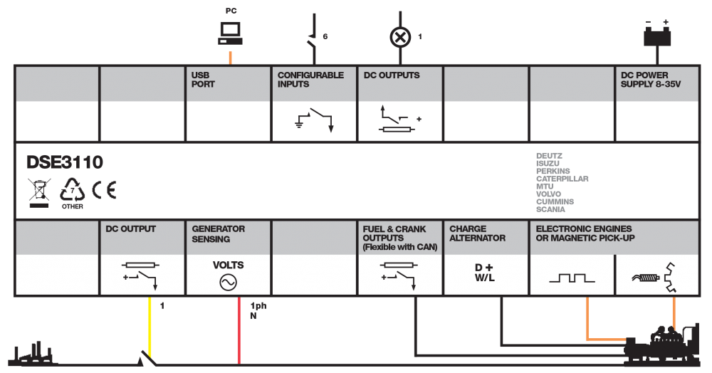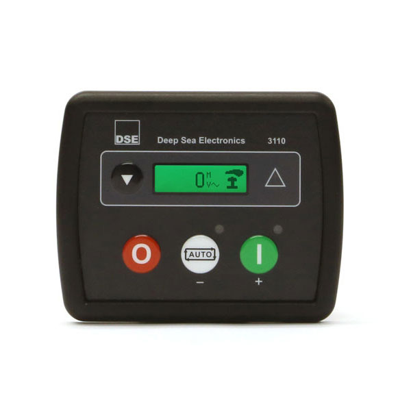
The DSE3110 is an outstanding compact control module that provides a comprehensive range of features for single-set applications. The controller can be used in manual or auto start mode.
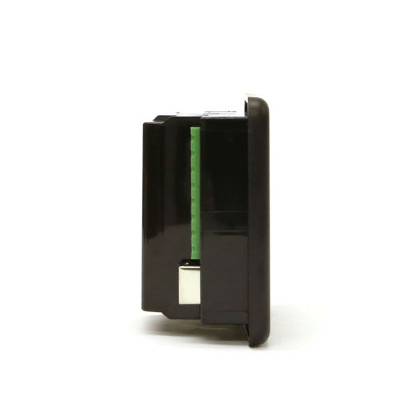
98 mm x 79 mm x 40 mm
(3.9” x 3.1” x 1.6”)
8.0 mm (0.3”)
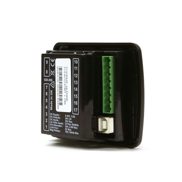
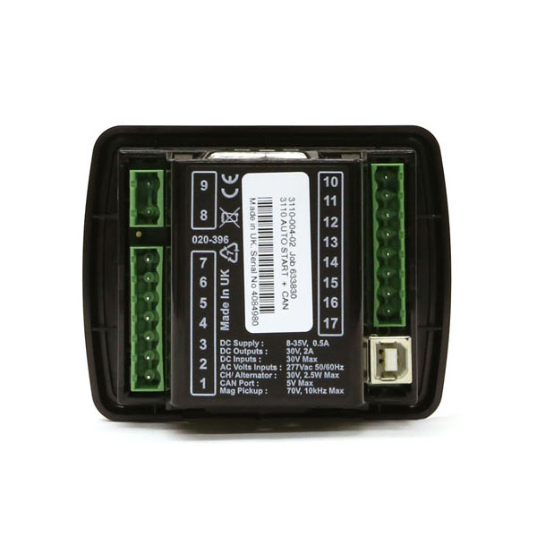
3110-02 – Manual & Auto Start Control Module (Can)
3110-01 – Manual & Auto Start Control Module (Mpu)
80 mm x 68 mm (3.1 ” x 2.7″)
0.16kg

| Key Features | Key Benefits |
|---|---|
| Standard engine and electronic CANbus variants. | Instant integration with both standard and modern electronically controlled engines. |
| Configurable inputs/outputs (6 digital inputs/4 outputs – 2 outputs configurable on magnetic pick-up variant). | Provides multiple installation options. |
| Remote start input. | Provides a simple connection to operate the generator from a remote location. |
| Comprehensive display parameters. | Provides instant notification of generator voltage, generator frequency, battery voltage, engine speed and run hours via one button navigation. |
| Engine pre-heat. | Warms the engine to a safe temperature at start-up to increase engine life. |
| Configurable timers & alarms. | Provides excellent system flexibility. |
| Large back-lit icon LCD display. | Displays information to the operator in a clear and concise format. |
| DSE Configuration Suite PC Software. | Provides complete user-friendly configuration and easy-to-use high-level system control & monitoring. |
| Additional Features |
|---|
| – LED & LCD alarm indications. | – Tamper-proof hours counter. |
| – Power save mode. | |
| – Alternative configuration. | |
| – Shutdown warning protection for multiple fault conditions. |
| DC Supply | OUTPUTS |
|---|---|
| CONTINUOUS VOLTAGE RATING 8 V to 35 V Continuous |
OUTPUT A (FUEL) 2 A DC at supply voltage |
| CRANKING DROPOUTS Able to survive 0 V for 50 mS, providing supply was at least 10 V before dropout and supply recovers to 5 V. This is achieved without the need for internal batteries. |
OUTPUT B (START) 2 A DC at supply voltage |
| CHARGE FAIL/ EXCITATION 8 V to 35 V fixed power source 2.5 W |
AUXILIARY OUTPUTs C & D 2 A DC at supply voltage |
| NOMINAL STANDBY CURRENT 35 mA at 12 V, 30 mA at 24 V |
|
| MAXIMUM OPERATING CURRENT 55 mA at 12 V, 60 mA at 24 V |
| GENERATOR | MAGNETIC PICK-UP |
|---|---|
| VOLTAGE RANGE 15 V – 333 V AC (L-N) |
VOLTAGE RANGE +/- 0.5 V to 70 V |
| FREQUENCY RANGE 3.5 Hz to 75 Hz |
FREQUENCY RANGE 10,000 Hz (max) |
| ELECTRO-MAGNETIC COMPATIBILITY | ELECTRICAL SAFETY | TEMPERATURE |
|---|---|---|
| BS EN 61000-6-2 EMC Generic Immunity Standard for the Industrial Environment. |
BS EN 60950 Safety of Information Technology Equipment, including Electrical Business Equipment. |
BS EN 60068-2-1 Ab/Ae Cold Test -30°C. |
| BS EN 61000-6-4 EMC Generic Emission Standard for the Industrial Environment. |
BS EN 60068-2-2 Bb/Be Dry Heat +70°C. |
| VIBRATION | HUMIDITY |
|---|---|
| BS EN 60068-2-6 Ten sweeps in each of three major axes. 5 Hz to 8 Hz @ +/-7.5 mm, 8 Hz to 500 Hz @ 2 gn. |
BS EN 60068-2-30 Db Damp Heat Cyclic 20/55° C @ 95% RH 48 Hours. |
| BS EN 60068-2-78 Cab Damp Heat Static 40° C @ 93% RH 48 Hours. |
| SHOCK | DEGREES OF PROTECTION PROVIDED BY ENCLOSURES |
|---|---|
| BS EN 60068-2-27 Three shocks in each of three major axes 15 gn in 11 ms. |
BS EN 60529 IP65 – Front of module when installed into the control panel with the optional sealing gasket. |