
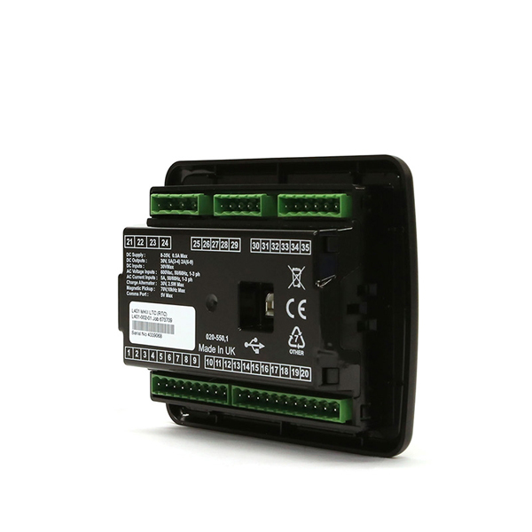
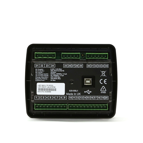
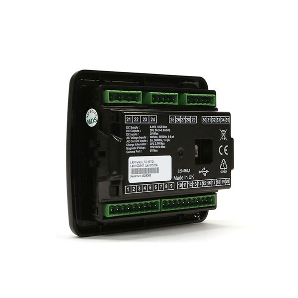
The DSEL401 MKII is an intelligent control module designed specifically for mobile lighting tower applications. The control module provides class leading flexible features that are fully configurable to suit multiple complex lighting sequences
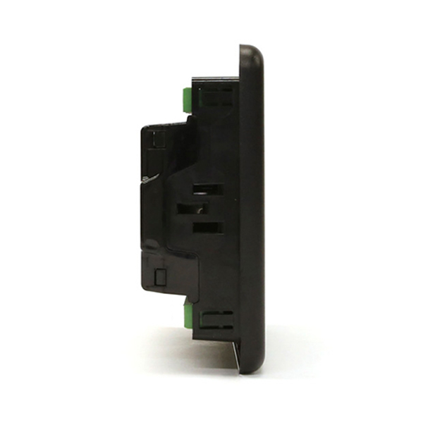
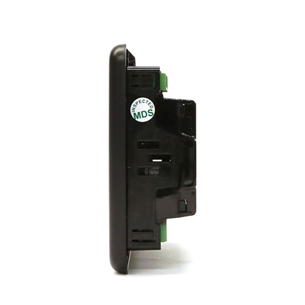
140 mm x 113 mm x 43 mm (5.5” x 4.4” x 1.7”)
8.0mm (0.3”)
L401-01 – L401 MKII Intelligent Lighting Tower Control Module (Rtc)
118 mm x 92 mm (4.6” x 3.6”)
0.28kg

| Key Features | Key Benefits |
|---|---|
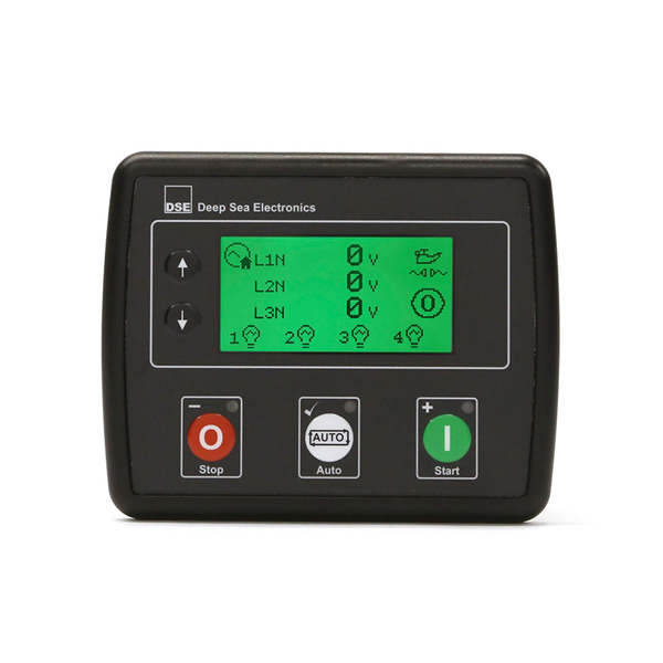
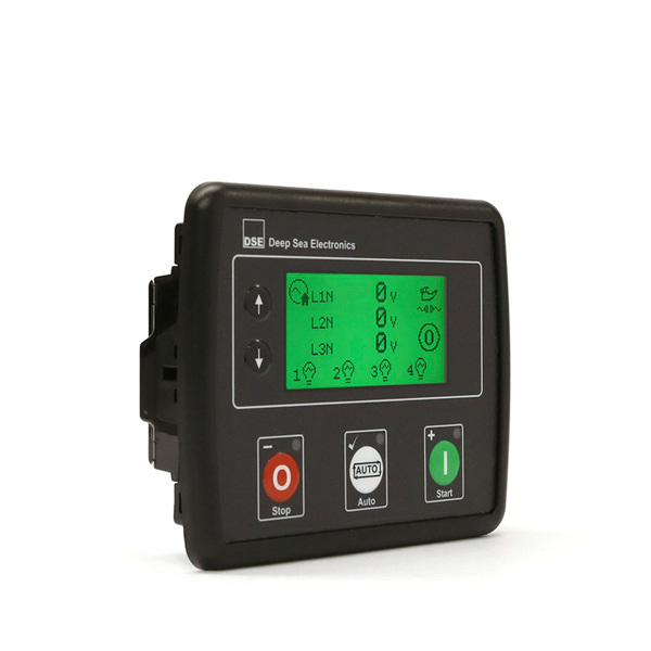
| Large back-lit icon LCD display. | Displays information to the operator in a clear and concise format. |
| Configurable outputs (8 DC, 3 analogue/digital). | Provides multiple installation options. |
| Configurable staged light control outputs. | Prevents engine from stalling. |
| Heated display option. | Ensures the display continues to operate in extreme cold weather conditions. |
| Power monitoring (kW h, kV Ar, kV Ah, kV Ar h). | Provides clear accurate power measurement information. |
| Automatic & manual light control. | Allows lights to be controlled manually or turn on automatically when daylight reduces (sensor required). |
| Individual lighting control. | Avoids permanent light failure during restart. |
| Light failure detection. | Informs the operator of the exact bulbs that need replacing. |
| Comprehensive fuel monitoring. | When fuel reaches a certain level the lights can be dimmed to increase available running hours. |
| Event scheduler (8). | Can be programmed to operate up to 4 staged load outputs. |
| Engine speed protection, engine hours counter, engine pre-heat, engine run-time scheduler, engine idle control for start/stop. | Ensures the engine is fully monitored for improved operating performance. |
| Start on low battery. | Ensures the battery does not fully discharge. Engine runs until battery is charged. |
| Configurable event log (50). | Provides access to historical alarms and operational status. |
| DSE Configuration Suite PC Software. | Provides complete user-friendly configuration and easy-to-use high-level system control & monitoring. |
| Additional Features |
|---|
| – Power save mode. | – Fuel & crank outputs. | – Alternative configuration (1). |
| – 3-phase generator sensing. | – CAN & alternator speed sensing. | |
| – Generator/load current monitoring & protection. | – Engine maintenance alarms (3). | |
| – 600 V ph-ph nominal system compatibility. |
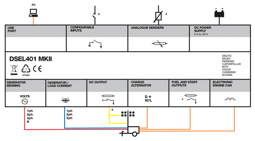
| DC Supply | OUTPUTS | GENERATOR |
|---|---|---|
| CONTINUOUS VOLTAGE RATING 8 V to 35 V Continuous |
OUTPUT A (FUEL) 10 A short term, 5 A continuous, at supply voltage |
VOLTAGE RANGE 15 V to 415 V AC (Ph to N) 26 V to 719 V AC (Ph to Ph) |
| CRANKING DROPOUTS Able to survive 0 V for 50 mS, providing supply was at least 10 V before dropout and supply recovers to 5 V. This is achieved without the need for internal batteries. LEDs and backlight will not be maintained during cranking. |
OUTPUT B (START) 10 A short term, 5 A continuous, at supply voltage |
FREQUENCY RANGE 3.5 Hz to 75 Hz |
| MAXIMUM OPERATING CURRENT 85 mA at 12 V, 96 mA at 24 V |
||
| MAXIMUM STANDBY CURRENT 51 mA at 12 V, 47 mA at 24 V |
||
| MAXIMUM SLEEP CURRENT 35 mA at 12 V, 32 mA at 24 V |
||
| MAXIMUM DEEP SLEEP CURRENT |
| ELECTRO-MAGNETIC COMPATIBILITY | ELECTRICAL SAFETY | TEMPERATURE |
|---|---|---|
| BS EN 61000-6-2 EMC Generic Immunity Standard for the Industrial Environment. |
BS EN 60950 Safety of Information Technology Equipment, including Electrical Business Equipment. |
BS EN 60068-2-1 Ab/Ae Cold Test -30°C. |
| BS EN 61000-6-4 EMC Generic Emission Standard for the Industrial Environment. |
BS EN 60068-2-2 Bb/Be Dry Heat +70°C. |
| VIBRATION | HUMIDITY |
|---|---|
| BS EN 60068-2-6 Ten sweeps in each of three major axes. 5 Hz to 8 Hz @ +/-7.5 mm, 8 Hz to 500 Hz @ 2 gn. |
BS EN 60068-2-30 Db Damp Heat Cyclic 20/55° C @ 95% RH 48 Hours. |
| BS EN 60068-2-78 Cab Damp Heat Static 40° C @ 93% RH 48 Hours. |
| SHOCK | DEGREES OF PROTECTION PROVIDED BY ENCLOSURES |
|---|---|
| BS EN 60068-2-27 Three shocks in each of three major axes 15 gn in 11 ms. |
BS EN 60529 IP65 – Front of module when installed into the control panel with the optional sealing gasket. |